
Marine Lighting EMC and EMI: Preventing Interference with Onboard Electronics
A LED marine lighting setup can seem to run perfectly. However, it can still produce electromagnetic noise in the background. This noise can disrupt navigation and radio communication on board. In order to maintain the stability of signals for all marine electronics, a complete plan has to be made. After that, test the radiated noise in the surrounding environment. Then tune the driver circuit layout to reduce interference. Finally, confirm the equipment meets marine EMC requirements using the right tests.
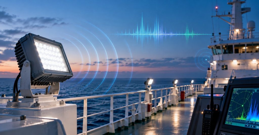
If you understand the process of this kind of interference and follow the protocol strictly, then shipbuilders and fleet members can choose suitable marine lighting designs and properly examine the technical documents before installing the lights.
Table of Contents
How LED Drivers Generate Electromagnetic Interference
Many LED driver designs rely on switched-mode power conversion to control LED current with good efficiency. The switching part turns on and off again and again. Those quick changes cause fast shifts in voltage and current. That can lead to electromagnetic noise.
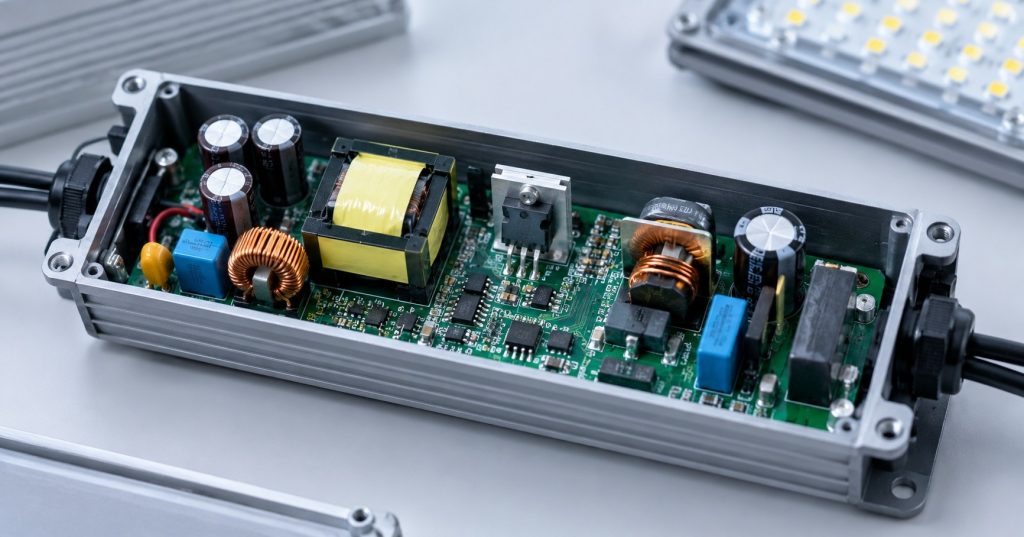
Three mechanisms deserve particular attention:
Switching transients and parasitic ringing
Once the switching transistor is turned off, the stored energy in the leakage inductance of the transformer and other parasitic elements may result to overshoot voltages and oscillations. High-frequency components are created by fast edges on switching. These can be minimized using snubbers, appropriate selection of components, and switching transients.
Transformer and parasitic coupling
The parasitic capacitance created between the primary and secondary circuits can also be a way through which the common mode current flows. The design of the transformer, the wiring, and the connection to the chassis will affect the emissions.
PCB current-loop geometry
A bigger loop with rapidly changing current will increase the magnetic coupling. Poorly designed return path as well as large switching-node area will increase the radiated emission. It is important to decrease the area of high-frequency loop and separate the noisy power stage from the control circuitry.
These interactions coexist amongst themselves. It is possible for the filter to block the conducted noise, but it is not possible to fix the problem when the noise is radiated due to cable or switching loop. The problem should be diagnosed first.
Common-Mode and Differential-Mode Conducted Emissions
Conducted EMI is not a single type of noise. Engineers need to distinguish common-mode (CM) and differential-mode (DM) current because the two require different suppression strategies.
| Characteristic | Common-mode noise | Differential-mode noise |
| Current path | In the same sense in respect to the chassis or other references in supply lines | Flows out via one supply conductor and returns via the other |
| Typical sources | Capacitance, switching nodes, and inadvertent chassis coupling | Switching pulses and ripple in the power conversion loop |
| Common countermeasures | Common-mode choke coils, appropriate capacitive coupling paths, and proper bonding | Inductance in differential mode, correct capacitor values, and optimizing input filter |
Common mode chokes have high impedance against common mode noise and should ideally allow differential supply current to pass with low impedance. Filters that employ differential-mode filtering on the other hand try to eliminate any noise present between the supply lines.
There could be instances where these modes may influence each other and actual filters exhibit parasitics. Measurement of the disturbance and separation of the modes using proper current probes or fixtures if needed before component selection is recommended.
Component selection should also consider the current and voltage ratings of the filters, heat dissipation issues, leakage current, and source impedance. Inadequately designed input filters could result in resonance or instability of a power converter.
VHF Interference: Why Switching Noise Can Affect Marine Radios
VHF communications on a marine vessel operate within the frequency range of 156 to 174 MHz. A much slower switching rate LED driver can, however, create VHF noise in its spectrum because it has harmonics and fast edge transitions that spread energy over the spectrum.
For instance, the radio can generate noise as the deck light is switched on or as the level of brightness is lowered. Possible sources of noise are emissions from the driver, common mode current in the marine lighting cable, coupled into the antenna feeder of the radio, or noise from the power supply of the receiver.
Frequency of the PWM itself does not help much to pinpoint the source of the problem. An effective way to investigate is to compare the emission spectrum in different modes and see if there is correlation between the peaks in the spectrum and any switching harmonics.
Engineers should check:
- Whether the interference follows a particular luminaire or driver.
- Whether it changes between full output and dimming modes.
- Whether noise is present on the supply conductors.
- Whether the driver, cable, or connector produces strong near-field emissions.
- Whether cable routing or antenna proximity changes the observed interference.
The correctives must follow immediately after the measurements are made. They could involve better input filtering, node ringing, common mode current on cables, or changing the cabling path and bonding of enclosures.
How to Configure EMC Tests for Marine LED Luminaires
An EMC report is meaningful only when the test method, product configuration, and acceptance criteria match the intended assessment.
Conducted-emissions testing
A proper EMI receiver or spectrum analyzer is used to measure interference on the supply feed lines. The line impedance stabilization network (LISN) is needed when stipulated by the test method and is used to define a measurement impedance and isolate the test circuit from any supply interference.
The test report shall state the frequency range, detector settings, supply conditions, measurement network, limits, and results. In case of marine products, the test method needs to be chosen in accordance with the applicable marine product standard and not based on a lighting test.
Radiated-emissions testing
Radiated emission testing is carried out through proper antenna systems, measurement receivers, and test environments. Probes in the near field can be used to find noisy components in a circuit board and cable in development stage, but these do not substitute radiated emission testing. The test set-up shall record orientation of the luminaire, cabling, enclosures, control accessories, operating modes, and measurement distances when required.
Operating modes and configuration control
Only testing at full brightness will overlook potential interference associated with dimming, start-up, shut-down, or a certain controller setting. The test program must define all relevant operating modes and justify why certain configurations are being tested.
In case of hardware that is close to its release, the driver, PCB version, enclosure, connectors, and cable configuration should resemble the final product. If there is any change later, the manufacturer must consider whether further testing is necessary.
The pre-compliance testing helps to identify possible issues before laboratory testing. It is a development tool rather than a replacement for compliance testing or marine certification.
Conclusion
EMC in marine lighting products requires the ability to control switching noise, know about common mode and differential mode current, cable coupling, and testing of the final product.
To marine lighting product makers, taking measurements and making circuit or layout changes is better than using filters and shields without diagnostics. To technical buyers, examining applicability of standard, test setup, measurement results, and traceability of the product gives a better basis of evaluation.
The main goal here is not only getting an EMC test report, but ensuring that the tested product and performance is suitable for the marine environment.
